
Chassis Dynamometer & Power Performance Testing Equipment
Vehicle chassis dynamometer | CTDCG-3/CTDCG-10/CTDCG-13/CTDCG-15
In vehicle testing and inspection facilities, installing undersized powertrain measurement systems creates operational bottlenecks, inaccurate road-load simulation, and safety risks during high-torque evaluation runs. A...


In vehicle testing and inspection facilities, installing undersized powertrain measurement systems creates operational bottlenecks, inaccurate road-load simulation, and safety risks during high-torque evaluation runs. An industrial vehicle chassis dynamometer operates as the core test bench for simulating tractive resistance, measuring wheel-end output, and analyzing full-vehicle powertrain behavior under controlled indoor conditions. Choosing an appropriate vehicle chassis dynamometer ensures that axle-load thresholds, power absorption ratings, and roller mechanics match fleet testing demands.
Facility directors, fleet testing engineers, and inspection operators must evaluate roller diameter, braking torque, and structural containment before committing capital. An improperly sized vehicle chassis dynamometer restricts vehicle throughput and impairs regulatory compliance. This engineering review examines verified mechanical specifications, operational principles, and integration practices for modern test bays.
Table of Contents:
1. Verified Equipment Definition and Application Scope
2. Technical Sourcing Parameters and Axle Capacity
3. Classification and Functional Testing Modes
4. Construction Materials, Quality Controls, and Safety Features
5. Practical Procurement and Inspection Line Integration
6. Frequently Asked Questions
7. Summary and Technical Consultation
1. Verified Equipment Definition and Application Scope
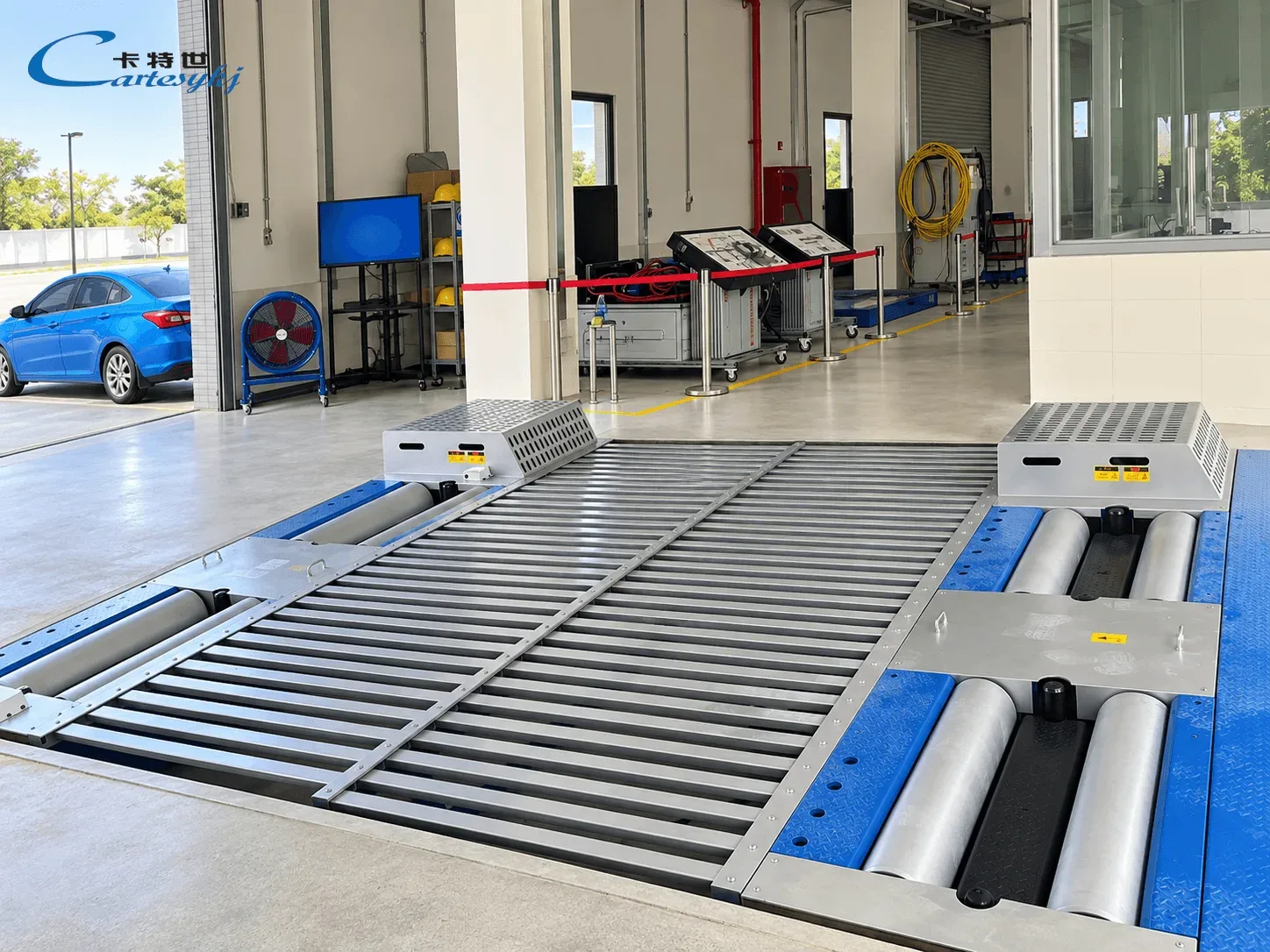
A vehicle chassis dynamometer is a specialized testing apparatus designed to evaluate complete vehicle dynamic performance, tractive effort, and emissions behavior while the vehicle remains stationary inside an inspection bay. The drive wheels rest directly on precision-machined steel roller sets that simulate road load, rolling resistance, and vehicle inertia under repeatable conditions.
Testing platforms support vehicle dynamic experiments, fuel economy experiments, structural reliability trials, and specialized transmission system investigations. Operating an vehicle chassis dynamometer allows technicians to detect chassis power output, braking torque, test speed, accumulated distance, acceleration time, and coast-down (sliding) distance.
When combined with auxiliary testing hardware, the unit operates as an emissions & fuel consumption testing dynamometer. Connecting an external exhaust gas analyzer enables emissions testing during steady-state or dynamic drive cycles, while integrating a fuel consumption meter permits multi-condition loaded fuel measurement under verified road loads.
2. Technical Sourcing Parameters and Axle Capacity
Selecting an vehicle chassis dynamometer requires matching roller dimensions, mechanical braking torque, and power absorption to target vehicle fleets. Cartesykj CTDCG series platforms deliver four distinct structural configurations spanning passenger cars to multi-axle commercial vehicles.
Model Max Axle-Load (kg) Max Absorption Power (kW) Max Braking Torque (Nm) Max Testing Speed (km/h) Drum Diameter x Length (mm) Center Distance (mm) Inside / Outside Drum Width (mm) Working Voltage & Current Power Supply
CTDCG-3 3,000 160 1,600 130 Φ216 × 850 480 700 / 2,700 96V × 35A 220V ±10% 50Hz
CTDCG-10 10,000 250 2,500 160 Φ320 × 1,000 600 700 / 2,700 96V × 35A 220V ±10% 50Hz
CTDCG-13 13,000 300 3,000 160 Φ373 × 1,100 600 700 / 2,900 96V × 35A 220V ±10% 50Hz
CTDCG-15 15,000 350 3,500 160 Φ452 × 1,100 600 700 / 2,900 96V × 35A 220V ±10% 50Hz
For passenger cars and light-duty vans, the CTDCG-3 vehicle chassis dynamometer supports a maximum axle load of 3,000 kg, absorbing up to 160 kW with 1,600 Nm of braking torque at speeds up to 130 km/h. Its dual rollers feature a diameter of Φ216 mm and length of 850 mm, with a center-to-center distance of 480 mm.
For heavy freight trucks, municipal transit buses, and multi-axle commercial transports, the CTDCG-10, CTDCG-13, and CTDCG-15 heavy-duty platforms provide axle capacities of 10,000 kg, 13,000 kg, and 15,000 kg. Power absorption scales from 250 kW to 350 kW, generating braking torque ratings from 2,500 Nm to 3,500 Nm at speeds up to 160 km/h.
Drum geometry expands alongside axle capacity. High-capacity variants employ roller diameters of Φ320 mm, Φ373 mm, and Φ452 mm to distribute heavy tire contact loads and control localized tire heat buildup during extended loaded runs. Center-to-center roller spacing increases to 600 mm on these units to stabilize larger commercial wheel profiles.
3. Classification and Functional Testing Modes
Industrial testing benches fall into two operational categories based on laboratory requirements: dynamic power performance dynamometers and emissions testing dynamometers.
Dynamic Power Performance Dynamometers
Power-focused systems evaluate wheel power output, drivetrain friction losses, transmission ratio steps, acceleration response, and coast-down resistance. Operators use these benches to measure peak tractive effort and drivetrain endurance under heavy continuous resistance.
Emissions and Fuel Consumption Dynamometers
Environmental testing configurations emphasize repeatable road-load simulation across standardized drive cycles. Connecting an exhaust gas analyzer and a fuel consumption meter allows an vehicle chassis dynamometer to quantify tailpipe emissions and measure multi-condition loaded fuel consumption.
Digital Architecture and Data Networking
The control software runs on standard Windows platforms, providing a user-friendly interface, real-time signal monitoring, and strong networking capability. The system automates routine testing procedures, retrieves historical inspection records, and prints standardized test reports without operator intervention.
4. Construction Materials, Quality Controls, and Safety Features
High continuous tangential forces generated during heavy deceleration require rugged roller construction, structural rigidity, and dependable tire containment mechanisms across the dynamometer bed.
Roller Balancing and Surface Durability
Each roller assembly undergoes high-precision dynamic balancing to suppress rotational vibrations at speeds reaching 160 km/h. Roller surfaces receive a wear-resistant coating with high joint bonding strength, providing an adhesion coefficient ≥ 0.92 to prevent tire slippage during high-torque loading.
Lateral Containment for Front-Wheel-Drive Vehicles
An vehicle chassis dynamometer incorporates adjustable gear wheel stops to ensure front-wheel-drive vehicles do not experience lateral slip during dynamic runs. These mechanical guides restrain lateral tire wandering, maintaining vehicle alignment on the roller bed.
Electrical Control Parameters
All CTDCG models share standardized electrical operational ratings. The load absorption circuit operates at 96V × 35A, while the central control console operates on a standard facility supply of 220V ±10% at 50Hz, simplifying laboratory electrical planning.
5. Practical Procurement and Inspection Line Integration
Sourcing an vehicle chassis dynamometer requires assessing civil pit installation, peripheral tool compatibility, and data integration within a complete vehicle testing bay.
Integration with Automotive Inspection Equipment
In high-throughput inspection stations, the chassis dynamometer operates alongside complementary Automotive Inspection Equipment. Station layouts frequently incorporate roller brake testers, suspension testers, sideslip plates, headlight aimers, and tailpipe exhaust gas analyzers linked to a central vehicle inspection database.
Working directly with an Automotive Inspection Line Manufacturer helps ensure that communication protocols, vehicle identification systems, and foundation geometry align across all station lanes without interfacing conflicts.
Civil Works and Foundation Sizing
Foundation design must accommodate the physical footprint of the roller assembly. Light models utilize an inner/outer drum frame width of 700 mm / 2,700 mm, while heavy platforms require 700 mm / 2,900 mm. Reinforced concrete pits must support dynamic shock loads up to 15,000 kg axle load, with dedicated channels for drainage and 96V power cabling.
Inspection Station Maintenance Routines
To preserve testing accuracy across high-volume inspection cycles, maintenance personnel should adhere to standardized mechanical and calibration procedures:
- Daily Inspection: Clean roller surfaces to remove rubber deposits and check the positioning mechanism of the lateral guide wheels.
- Monthly Checks: Inspect 96V internal wiring connections, verify software zero-point settings, and inspect data communication links.
- Periodic Calibration: Perform full-scale torque calibration using certified calibration arms and check dynamic balance on high-speed rollers.
Frequently Asked Questions
What parameters does an automotive chassis dynamometer measure?
An automotive chassis dynamometer measures chassis power output, braking torque, vehicle speed, total simulated mileage, acceleration time, and sliding or coast-down distance. Auxiliary meters measure multi-condition fuel consumption and tailpipe exhaust emissions.
What distinguishes performance dynamometers from emissions dynamometers?
Performance dynamometers evaluate tractive power output, drivetrain losses, and acceleration dynamics. Emissions dynamometers apply precise road-load resistance profiles to evaluate exhaust gases and fuel consumption across standardized driving cycles.
What axle load capacities are available for heavy commercial vehicles?
Commercial configurations include 10,000 kg, 13,000 kg, and 15,000 kg maximum axle load platforms, providing power absorption up to 350 kW and braking torque up to 3,500 Nm at speeds reaching 160 km/h.
How do roller coatings prevent tire slippage during test runs?
Rollers undergo high-precision dynamic balancing and feature a wear-resistant surface coating with high bonding strength, delivering an adhesion coefficient of 0.92 or higher. Adjustable gear wheels further prevent lateral vehicle slip.
What electrical power supply is required to run the testing system?
The dynamometer control console connects to a single-phase 220V ±10% 50Hz electrical supply, while internal power absorption circuits operate at 96V × 35A.
6. Engineering Conclusion and Consultation
Selecting an vehicle chassis dynamometer with verified axle load capacity, high roller adhesion, and reliable power absorption is essential for building an efficient vehicle testing bay. Choosing the appropriate vehicle chassis dynamometer configuration ensures test accuracy, operational safety, and full compliance across light and heavy commercial vehicle fleets.
Contact our engineering technical team for pit foundation drawings, detailed electrical schematics, and model configuration guidance tailored to your inspection line requirements.
Related Products
Compare related inspection systems
Chassis Dynamometer & Power Performance Testing Equipment
2WD/4WD Chassis Dynamometer | CTDCG -3J/CTDCG-3-4WD
View Product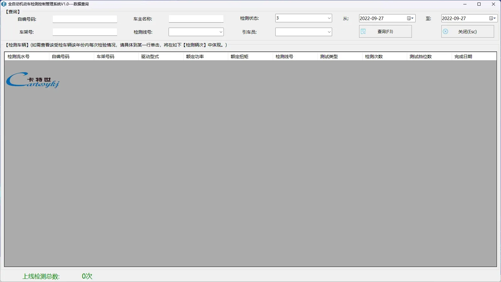
Chassis Dynamometer & Power Performance Testing Equipment
Motorcycle single-roller/double-roller horsepower dynamometer | CTMTDCG-3W/CTMTDCG-10W
View ProductRequest a Quote
Request configuration and pricing for your project.
Share your vehicle type, inspection lane layout, target capacity, and required model configuration for Vehicle chassis dynamometer | CTDCG-3/CTDCG-10/CTDCG-13/CTDCG-15.
Share the project location, vehicle types, inspection scope, applicable standards, target throughput, site conditions and current stage. We will confirm the configuration scope before discussing pricing.